01 Imaging
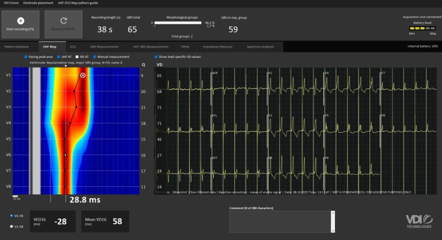
UHF-ECG Activation Map
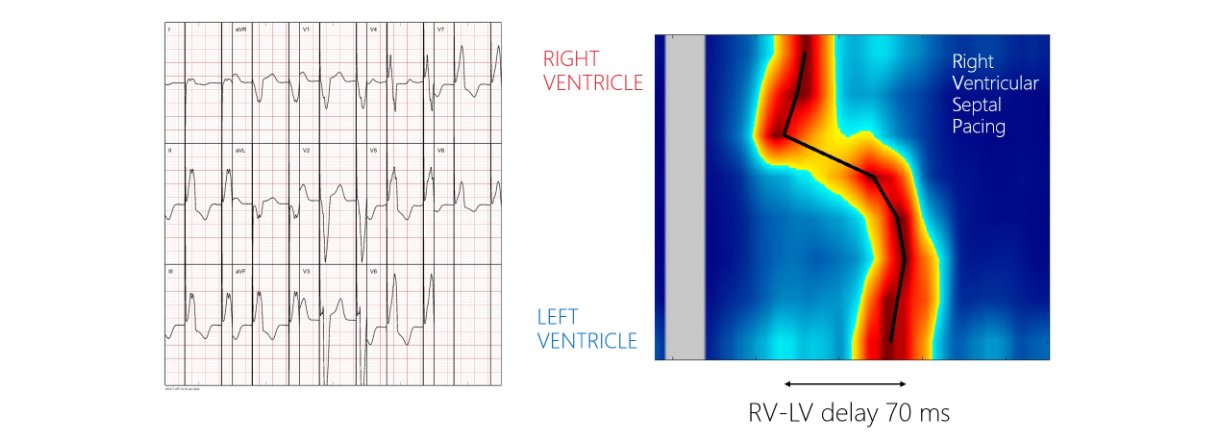
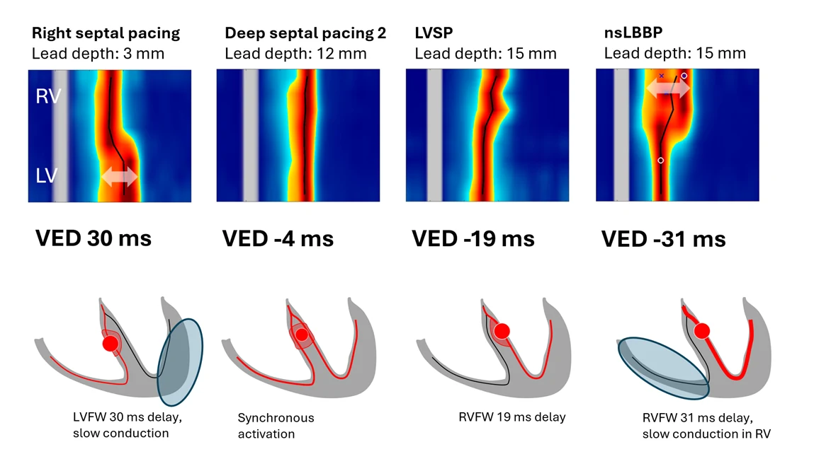
Clearly visualizes ventricular activation patterns, differentiating right from left ventricular conduction with millisecond precision.
A 30-second confirmation when ECG morphology leaves room for doubt, non-invasive, real-time, decisive.
Clearly visualizes ventricular activation patterns, differentiating right from left ventricular conduction with millisecond precision.
Standard 12(14)-lead ECG with real-time VDI visualization. Step-by-step lead depth guidance, it could not be easier.
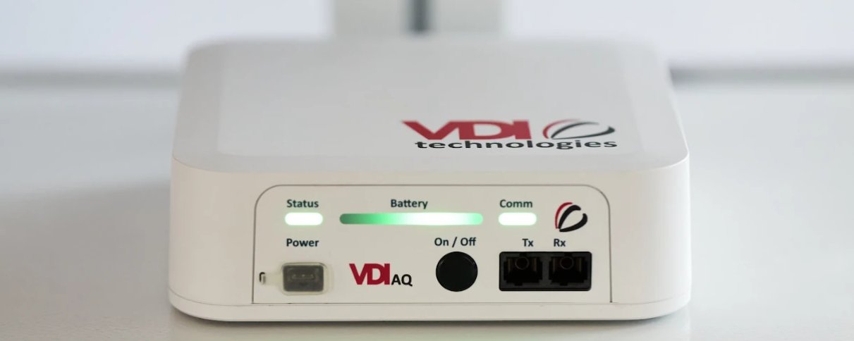
Capturing ultra-high-frequency ECG signals far beyond the standard ECG band, compact, wireless, and built for the EP lab environment.
Comprehensive mapping software that transforms raw UHF-ECG signals into vivid activation maps, guiding optimal lead placement in real time.